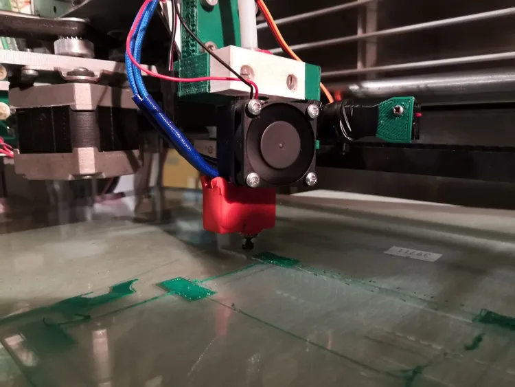
3D Printer from a DVD Vending machine
From DVD Vending machine to a Huge 3D Printer?
That’s the intent of this project.
Project description
Mechanical Structure
The starting point of this project is the vending machine that was very kindly gifted to me.
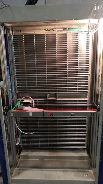
The mechanical structure is the one shown in the image by the side, with the final axis of the printer are overlaid on top of it.
The picture also shows the DVD racks, and the same structure was symmetric on the front, except for the frontend of the machine for the customers, that required a bit more of non-racked space.
Now, thinking about what is the size of a DVD cover… can you guess the total size of this metal box?
It spans over 2 m in height, and has a width of over 1.5 m!
Sadly, though, the depth (
…yes, I’ll need to work on that.
Electrical Structure
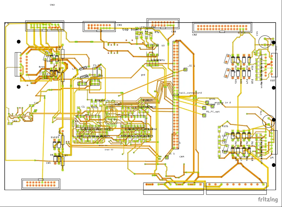
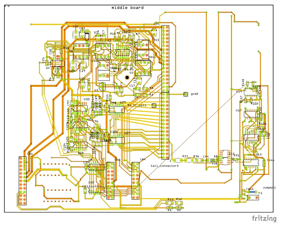
The original electrical system was build on three layers of PCBs:
- The top one, was responsible for the interface with the sensors and motors.
- The middle board was used to convert digital to analog signals, communicate via serial RS232 interface, and condition the sensor signals arriving from the layer atop.
- The last layer finally incorporates the logic processor, the memory IC and was responsible for controlling the entire system.
| top board | bottom board |
|---|---|
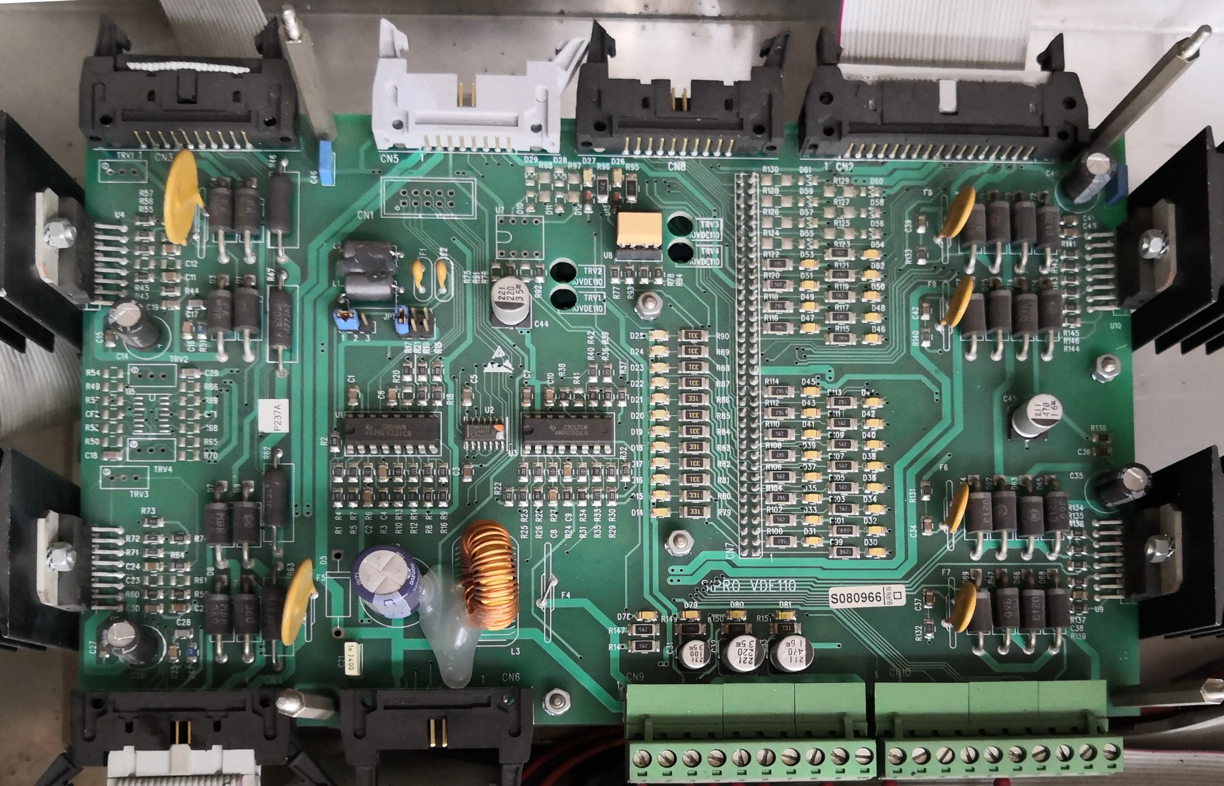 | 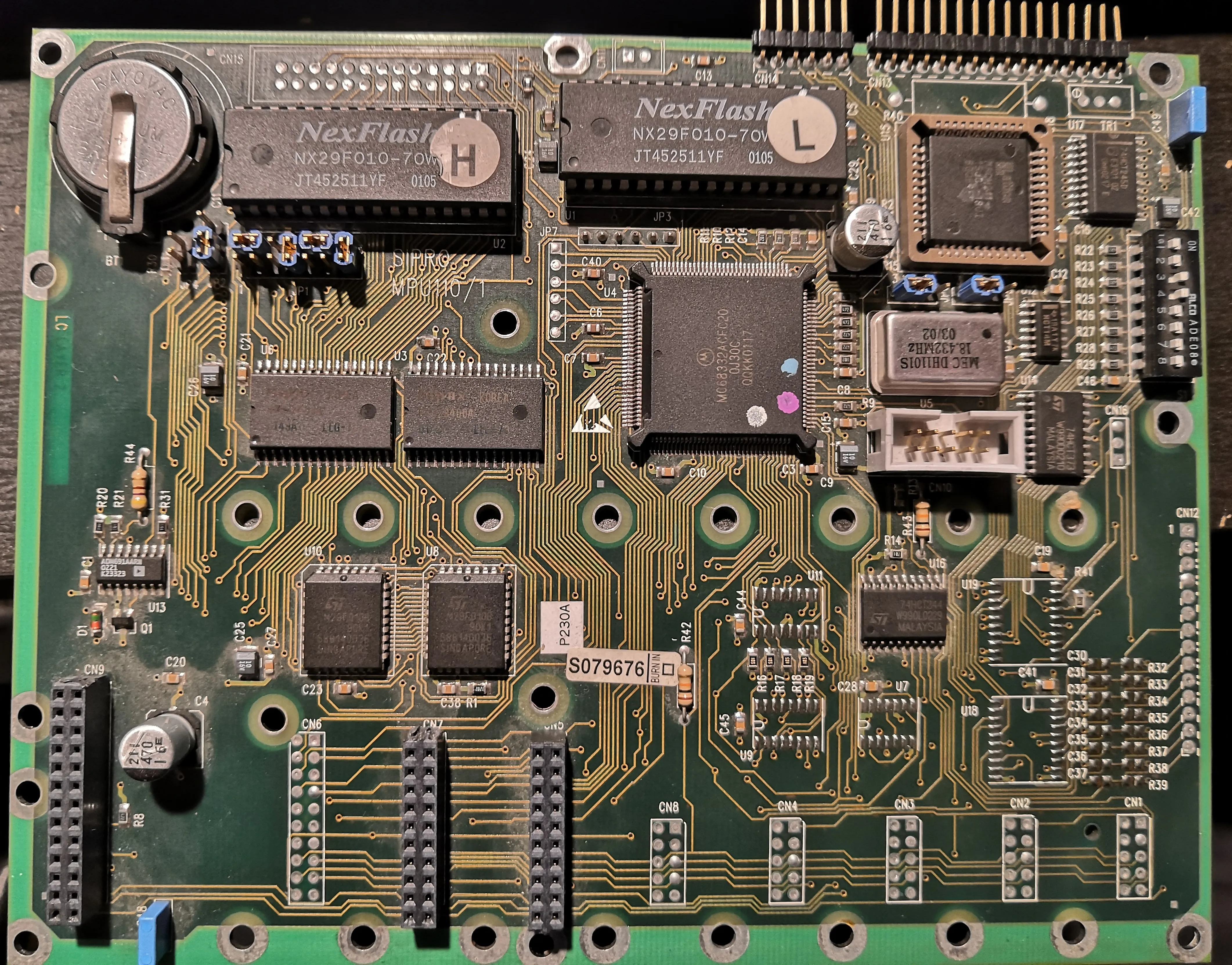 |
Motors
The motors used are all DC motors, 6 in total, but only 2 of them have encoders, whereas the others were just used with end stops to accomplish simple tasks.
Challenges
In order to make this metal box a fully functional 3D Printer, some issues needs to be solved, as it is not as easy as it could seem.
These two DC motors with encoders are the one that drive, through a timing belt,
the carriage that moves around the
Electronic Interface
The electrical interface was the first big problem to overcome. As explained previously in Electrical Structure, the original system was composed of 3 PCBs, and so I started reverse-engineering them.
This took a while, but I really enjoyed the process. From it, I discovered some quite clever discrete digital circuits used to make some simple functions, like a set-length pulse on a rising edge, or some exotic chip-selector logic, without the employment of a microcontroller.
In the end, I was able to reconstruct what I needed to control the machine. In particular, I only really needed to get the Inputs to control the motors, their encoders outputs, and some other outputs, like end stops and
- Top Layer:
- ICs working as interfaces for the encoders and signals
- Power routing
- Middle layer:
- Chip selection logic
- Command inputs from the logic layer
- Output of encoders to the logic layer
- Output of other digital signals (in I2C)
- Power routing outputs
| top board | middle board |
|---|---|
 |  |
The reverse engineering work, let me connect with an Arduino Uno to the middle layer board, in order to control the motors and read the other sensors that were present on the machine.
DC Motors
The motors that are used the most in the 3D printing field are the stepper motors. That is because they can achieve high precision movement together with relatively high torques. Moreover, their drivers are cheap, and makes them very easy to drive, requiring only a simple pair of signals, in open loop.
I wanted to use the motors that were already present in the original machine. This is because they had all the system already build to drive them, making in turn the required amount of work (in theory) pretty small.
Moreover, my original though was that being already embedded in the system, they were designed and sized appropriately. It turned out to be true, but also a weakness: for those wandering, you do not require high precision encoders to pick and place DVDs, especially in a very controlled environment, and you engineer the picker well enough.
They in fact had 50 CPR (Count Per Rotation), but at least they were mounted on the motor shafts, and not after the gearboxes, ending up providing 2670 CPR. This could seem as a high number, as stepper motors by default can do 200 steps/rev, but also the most common drivers let you control them at 8x or 16x mode, not to mention 32x or 64x for more higher-end drivers.
The other very important element in the motor mechanical loop, is the pulley diameter. This in fact is the last element in the chain, that moves the timing belt. The diameters for this machine are such that at the end of the day, the final step size results in being ok, but not excellent.
The results can be seen in the following table, where the final steps/mm can be compared to those of stepper motors driven at common microstepping values.
| description | steps/rev | steps/mm | mm/step |
|---|---|---|---|
| DC / | 2670 | 36.95 | 0.0270 |
| DC / | 2670 | 26.56 | 0.0376 |
| stepper - 8x | 1600 | 22.08 | 0.045 |
| stepper - 16x | 3200 | 31.74 | 0.031 |
| stepper - 32x | 6400 | 88.32 | 0.011 |
Size
Size does not matter, right? Well… in this context they do.
Most of the first cheap 3D printers, could still achieve a reasonable amount of precision due to the small scale (~20 cm axis) of their components. Firstly due to costs reason, as tight tolerance is not cheap, so the smaller the component, the better. This applies very easily to linear rails: their cost per length can be very prohibitive.
The other problem that start showing up at a bigger scale (1 m), is the components bending.
If the horizontal (
Another problem that arises by scaling up a 3D printer lies in the printing bed. This is due to the fact that it needs to be flat, for the same reasons as before, but it is easier to have a small amount of bending in a larger printing bed.
These points can be addressed by measuring the bed surface from the printer nozzle, that can be done sufficiently easily, and build a correction matrix to cope with the non-idealities.
Work done
- Blog Article 1: My 3D Printer moves!
- Blog Article 2: 3D Printer first prints
Future work
- Make it work completely
- Substitute Arduino UNO with STM32G4